
|
|
|||||||||||||
|
|
|
||||||||||||
![]()
![]()
![]()
![]()
![]()
![]()
![]()
![]()
![]()
![]()
![]()
![]()
![]()
|
It's hard to believe that it has been 2 years since I started building this
1/5 scale PT-19 WWII-era primary trainer model from a Dynaflite kit. I made
some good progress at first, reported in the April 2009 club newsletter. At
that time, I had the fuselage about 1/2 done. The left and right wing panels
were each about 1/2 done, too. To recap -- the model has an 89" wing span; a fuselage length of 69"; a projected weight of 11.5 to 13.5 lbs. The wing area is just under 1200 square inches. The wing loading should be 22 to 26 ounces per square foot. Power requirements are a 1.08 to 1.5 cubic inch 2-stroke, a 1.2 to 1.6 cubic inch 4-stroke, or a 25 cc gas engine. I plan to put an O.S. 1.08 (BX-1) 2-stroke engine in it. The engine will be side-mounted and equipped with a Slimline pitts-style muffler.
After neglecting this project far too long, I just completed some major
work on the wing. I built and temporarily mounted the ailerons. I
designed and installed the aileron servo mounts and control linkages in
the lower surfaces of both wing panels. I attached, carved, and
rough-sanded the solid-balsa wing tips. I then epoxied the 2 panels
together with plywood dihedral braces (photo #1).
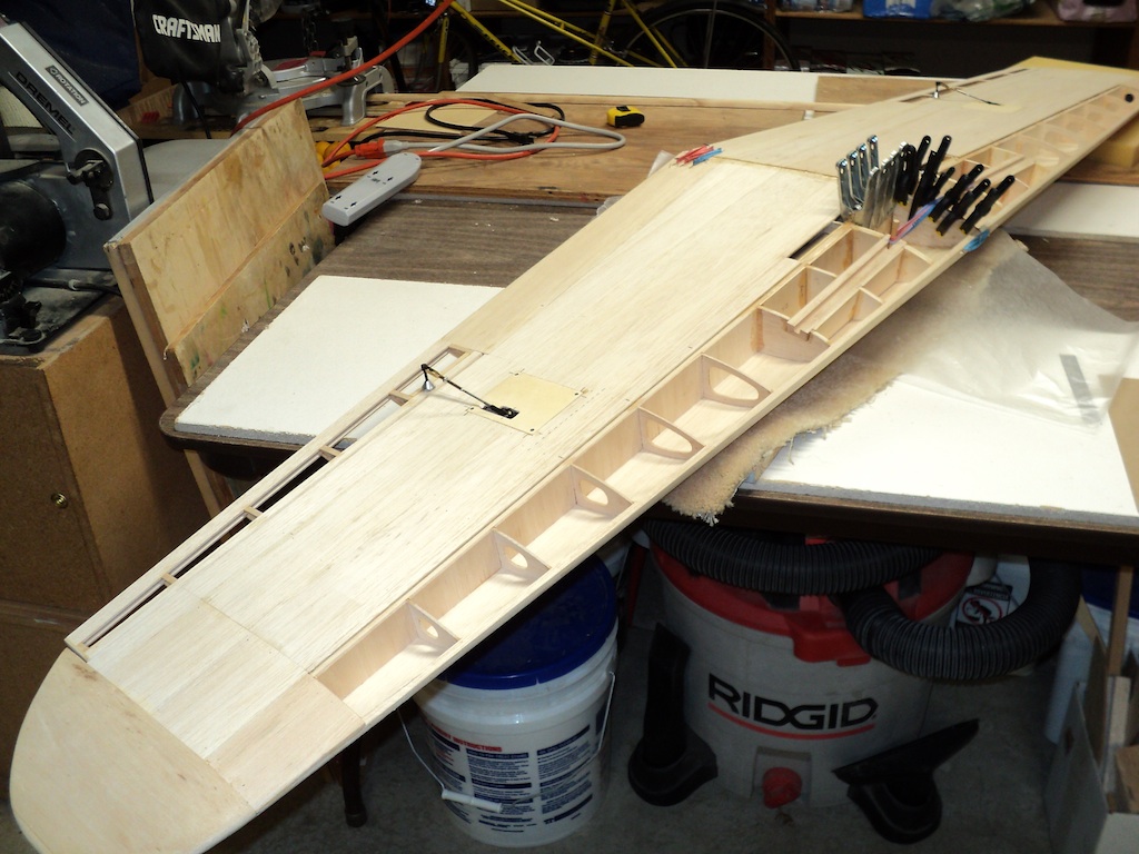 Incidentally, I find the construction sequence on this wing to be very unusual. With most model kits, you join the separate panels from the topside with one panel pinned down to the building board. The tip of the other panel is then raised up to give the proper dihedral angle. Everything stays pinned down while the glue sets. Not this kit! The panels are joined while off the building board, upside down -- with no way to pin-down the assembly until the glue sets. Just use a slow epoxy (30 minutes minimum) so you have enough time to glue, align, pin, and clamp everything together before the glue sets! Here is a close-up photo (#2) of the center section. Note that I used some short sections of 1/4" wood dowel and rubber bands to help pull the panels together at the center joint. The dowels were inserted into holes already drilled in the landing gear mounting blocks for the 5/16" main gear. The 2 plywood dihedral braces were previously glued to the right wing panel main spar -- after "dry fitting" everything together to assure a proper joint. 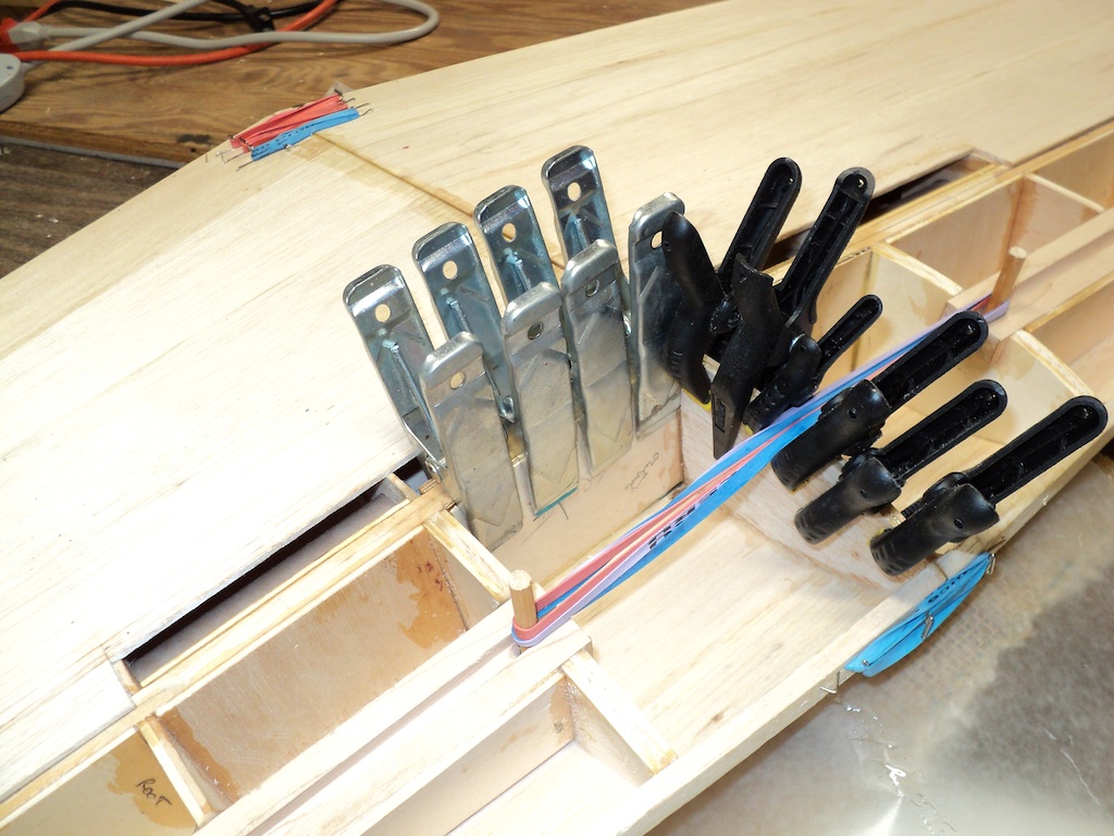 The next photo (#3) shows one of the ailerons, servo mount hatch, and control rod. The servo is mounted sideways on the underside of the hatch. I had to make the control rod exit slots in the hatch a little oversized to clear the servo control horn. The tip is just visible with the ball-link bolted to it. The next time I mount aileron servos like this, I think I will try to mount them deeper in the wing (more space between side of servo and hatch). Then the servo horn will be completely inside the wing, so the control exit slot can be smaller. 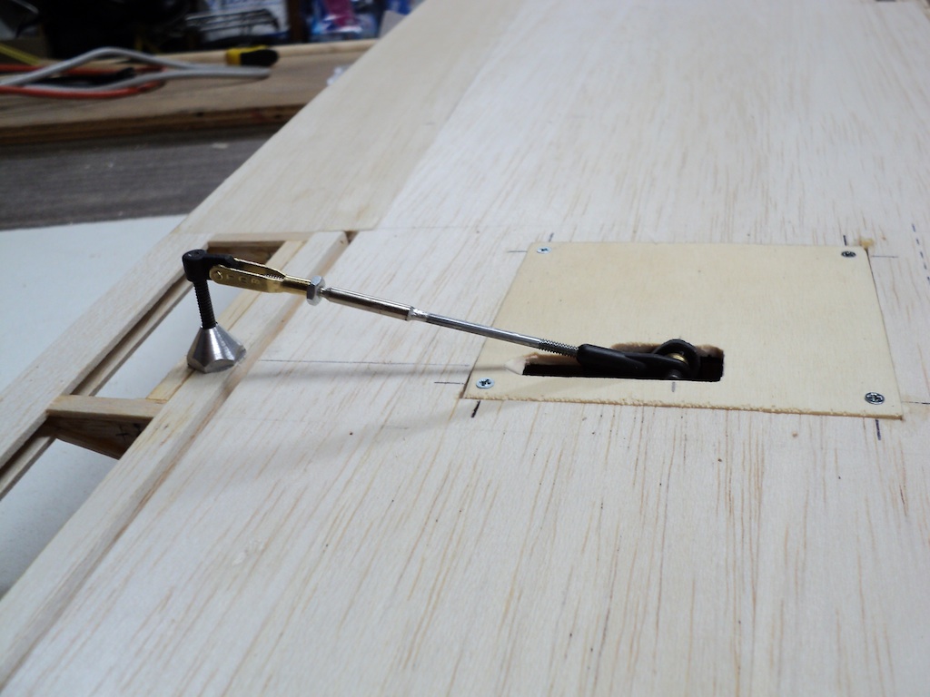 The clevis pin is attached to the aileron control horn directly over (or under) the aileron hinge line. The servo horn is canted forward about 30 degrees from vertical. This arrangement gives the aileron a 66% differential when deflected by the servo. That is, the aileron moves upward 3/4" (100%), but moves downward 1/2" (66% of 3/4"). Aileron differential is used to prevent an adverse-yaw situation. (Adverse Yaw = Right aileron causes left bank; Left aileron causes right bank. NOT good!) On a non-symmetrical airfoil wing, the downward deflecting aileron causes more drag than the upward deflecting one. This can cause "adverse yaw" unless it is countered with rudder-control or aileron-differential.
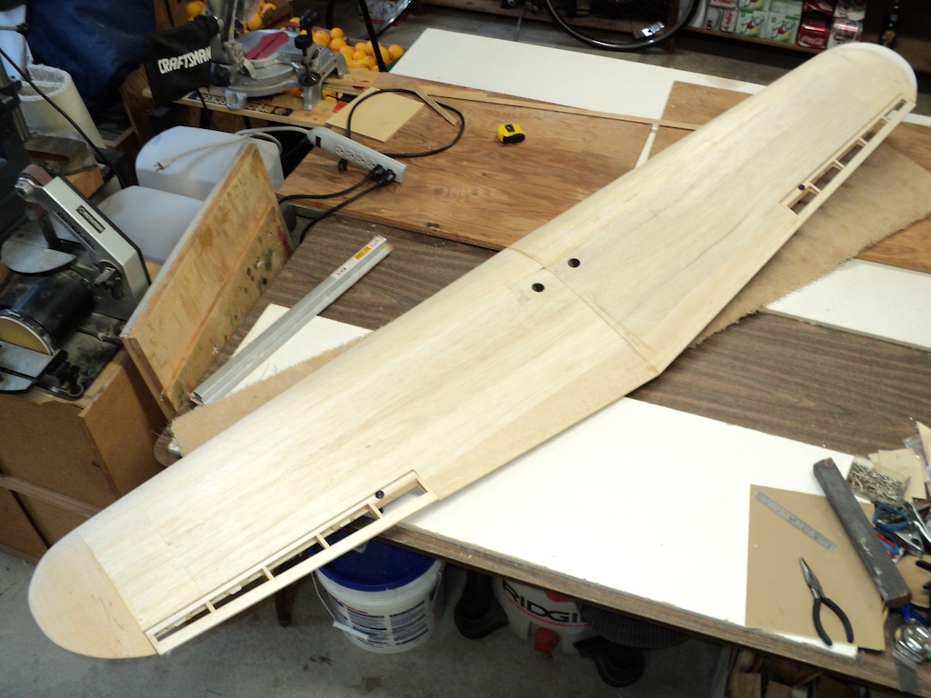
The next photo (#4) shows the upper surface of the wing after I removed
all the clamps and rubber bands. It really is 89" tip to tip. The 2
round holes near the center are exit holes for the aileron servo cables.
I used 3/4" rocket body tubes as conduits between the root-bays and the
aileron servo bays.
 The next 2 photos (#4 & #5) show front and rear views with the fuselage positioned on the wing. The fiberglass engine cowling sure helps to dress it up! 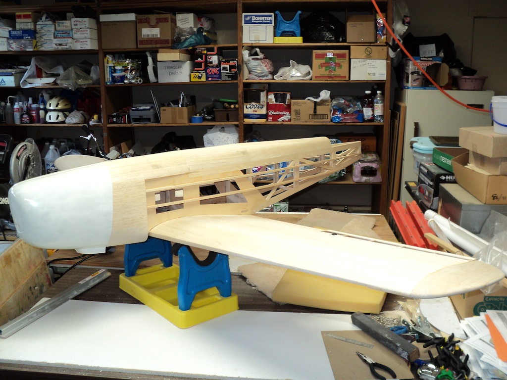 My shop space is being taxed to the limits with this model! 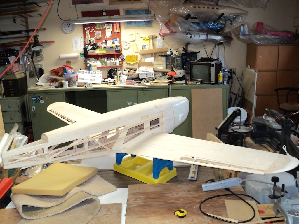
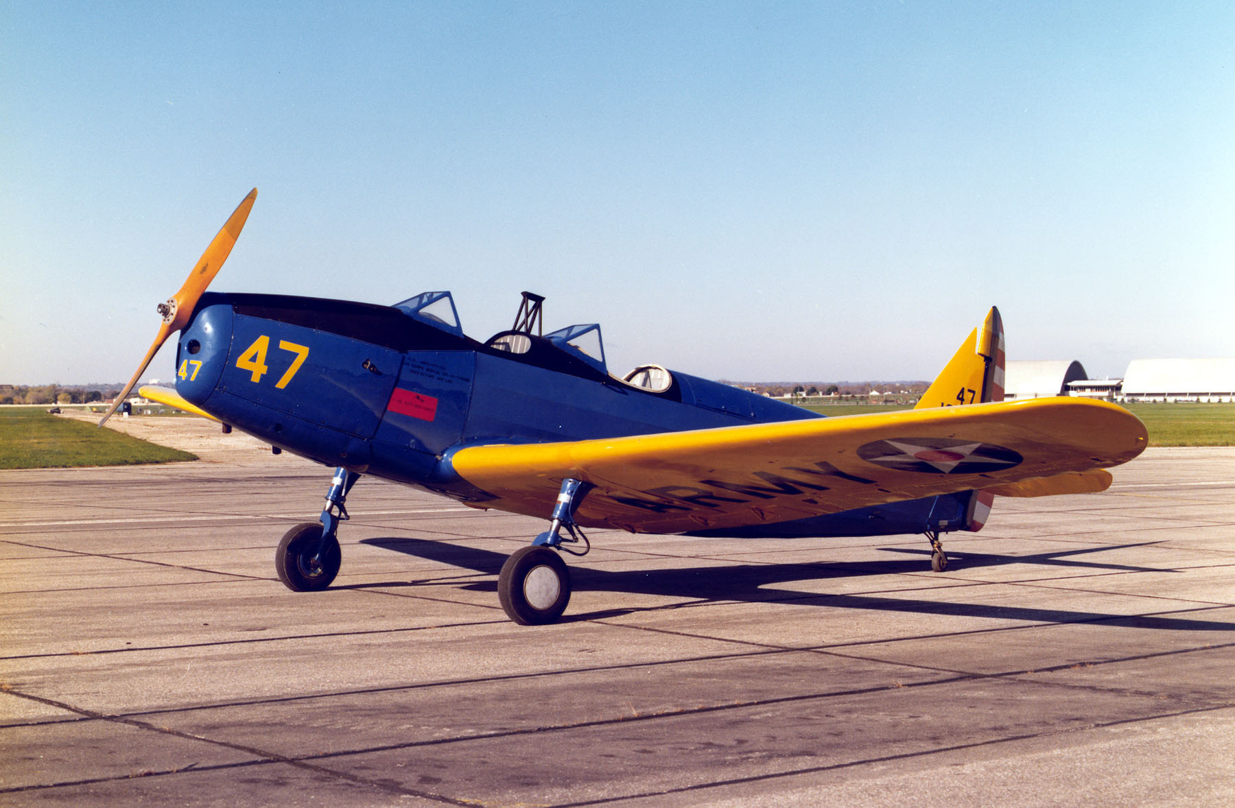
This last photo is what I hope my model will look like when finished.
It's a real PT-19 located in the National Museum of the US Air Force at
Wright-Patterson AFB in Ohio.
 There's still a long way to go before it's done. My goal is to have it completed by early May, this year. That will allow me time to put in a few test-flights and work out any kinks in the system before attending the 2011 IMAA West Coast Festival at Castle AFB on the Memorial Day weekend. That's the plan.
Ed Morgan
|